|
Below are some photographs & images of my Station and Equipment
Please note that each image on this page is linked to a larger, high-resolution, image. Smaller images are displayed here to enable faster loading.
Clicking on any image will result in a high-resolution image opening in a separate browser window.
My Antennas
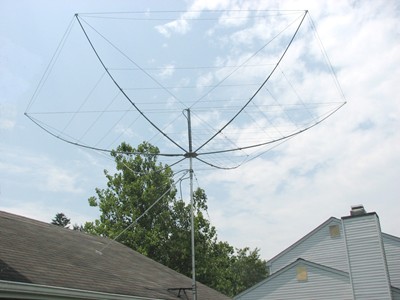
When I was preparing to return to HF operating in 2006, I spent a long, long time
researching various options for antennas. Although I am not faced with severe antenna
restrictions, I do live is a community of single family homes on building lots of
18,000 to 20,000 square feet each. When I stumbled across a discussion of the Hex Beam,
it seemed to fit my needs perfectly:
- Wire elements
- Easy home costruction
- Light Weight
- Full element lengths - No Traps
- Low wind resistance
- Comparable performance to a 2-element Yagi
My first "test" tri-band hex beam was built from crappie fishing poles in 2006.
It worked so well, that I built an improved 6-band Hex Beam in the summer of 2007.
Click Here for a whole page of
details and photographs of the construction of that Hex Beam
Leo Shoemaker, K4KIO, and Steve Hunt, G3TXQ, provided outstanding advice and counseling
throughout both construction projects. Please visit their websites for additional details
on HexBeam construction, tuning, and performance.
Update Note: I am currently on my third Hex Beam - one built and sold by Leo
Shoemaker, K4KIO. The homemade Hex Beams worked well, but the wooden bases did not hold up to the
weather.
One advantage of Hex Beams is that they are extremely light weight and have very
little wind resistance. Many Hams rotate their Hex Beams with light weight rotators
sold for turning TV antennas.
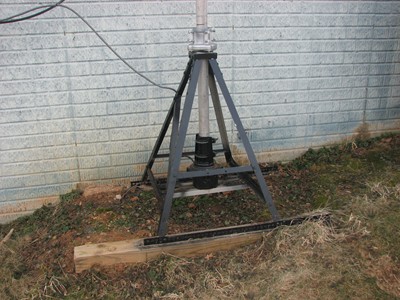
This mini tower and Yaesu G-450A rotator is a bit of over engineering, but it was
a fun two-weekend project. The stand is constructed from 1-1/4" angle aluminum stock
and 1" flat aluminum bar stock purchased from a local Ace Hardware store.
What really drove me to build this stand was the strong desire I had to use a thrust
bearing to keep the weight of the antenna and mast off the rotator.
Construction became a lot easier after I realized that the sole purpose was to support
the thrust bearing above the rotator. Once I had that realization, construction actually
progressed from top down. The first task was to build a square base to hold the thrust
bearing. Once the bearing base was built, then it was really on-the-fly designing and
construction as the legs were built and braced.
The thrust bearing is roughly 32 inches above ground level and about 16" above the top of the rotator.
The stand was completely built in my basement and was moved outdoors and mounted on
top of 4"x4" landscaping ties set on level soil.
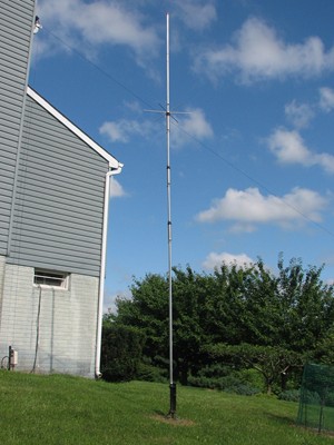
Shown here is a 5-Band Trap Vertical Antenna (Hustler 5BTV) that covers the 80M,
40M, 20M, 15M, and 10M Ham Bands. There is a top resonator that is attached to add
80M to the antenna, but I seldomly use it.
This vertical antenna was first installed in December, 2006, in an early attempt to start operating on the lower frequency bands -
the bands that are too low for the Hex Beam.
I had very limited success with this antenna until June of 2009 when I added a set
of 16 radials - one 10' long, one 15' long, ten 25' long, and four 50' long radials.
I have read several articles about proper vertical radial installation and decided to
try a compromise lay out. All sixteen radials are made from 14 AWG insulated, stranded
wire and are buried 2 to 3 inches in the ground. The twelve shorter radials are arranged
at approximate 30-degree increments around the base of the antenna. The four 50' radials
are arranged as best as the land plot allows
Immediately after adding the radials, I had to slightly adjust the lengths of the
various segments of the trap vertical and could see significant changes in the
antenna's SWR. I could also tell that the antenna was "hearing" much better than
before. After adding the radials, I have had good luck with the vertical on the 40M
band and am using it more now than before.
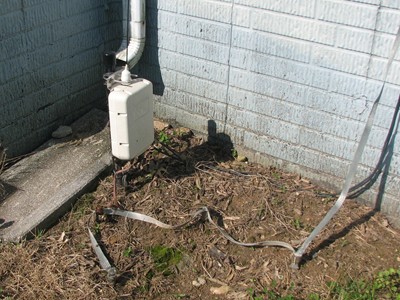
If you look very close at the bottom left corner of the picture, you can see the
Icom AH-4 ground-mounted random wire matching unit that interfaces to the 110 foot
long random wire discused below. If you zoom on the picture, you can actually see the
wire leaving the top of the AH-4 and going vertical to the roof edge.
As mentioned above, after getting on the air on the 20M through 6M bands with the
Hex Beam, I kept searching for a way to get on the lower frequency bands. The vertical
antenna discussed above was the first attempt, but did not provide the performance I
was seeking.
In the Spring of 2007, I did a lot of reading and decided to try the Icom AH-4
Random Wire Antenna Matcher. The unit interfaces seamlessly with the Icom IC-756ProIII
Transceiver and provides automatic remote tuning of random wire lengths and loops.
My first attempt to use the AH-4 unit was with a closed loop in the attic of the
house. The matcher worked well, but I ended up with a lot of RF in the house - enough
to set off the smoke detectors. So, another configuration was necessary.
After more reading and research, I decided on a 110-foot long random wire. The
radiating wire goes directly up from the AH-4, approximately 25 feet where is passes
through a pulley and then heads close to true North to a tree in the back yard. As a
counterpoise for the antenna, there is a set of four eight-foot length copper clad
ground rods tied together with 1" tinned copper ground strap.
The 1" tinned copper briad also comes into the radio shack and serves to provide a common electrical ground for the station.
This 110 foot long wire and AH-4 tuner combination has provided superior results for
me and has allowed me to operate on the 160M, 80M, 40M, and 30M bands. The combination
also provides a secondary antenna for 20M through 6M, but is seldom used on those upper bands.
My Radios
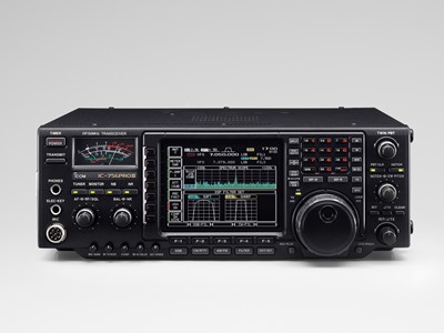
When returning to the hobby after an extended QRT period, I spent a long time looking into a good radio and looked at a wide variety of options.
I purchased an Icom IC-756PROIII HF plus 6M Transceiver from Ham Radio Outlet in
New Castle, Delaware, in July 2006. After more than seven years of operating this radio,
I can only say "wow !!!". I have never regretted the investment and still have this radio in the shack
Note: I have found it fairly difficult to take a real photograph of the front panel - This is actually a "file photo" from Icom.
In the seven years of almost daily operation, this rig has developed only one
condition requiring repair. It started displaying symptoms of lower than rated RF power
output on higher amateur bands (17M through 6M). A local Ham (KC3VO) troubleshot to a
defective driver transistor (type 2SC1972). After replacing both driver transistors with
a matched set of replacements from NTE (type NTE343), the radio provides full RF output
power and continues to provide flawless operation.
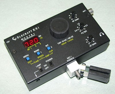
During the several weeks that the Icom 756ProIII was down for the replacement of the driver transistors, I started looking for additional operating options.
I ended up building this Elecraft KX1 QRP Transceiver.
This small (1-1/2" H x 5-3/8" W x 3" D) transciver has an internal antenna tuner
and outputs approximately 4 Watts when running from an external 13.8 VDC power supply.
It also runs off 6 "AA" batteries and puts out about 2 Watts when running off the
internal batteries.
The radio is designed for backpacking or hiking and provides a light for logging
and writing in poor lighting. The transceiver comes as a build-it-yourself kit with
excellent instructions and is a fun and challengiong project.
Click Here for a whole page of
details and photographs of the construction of the Elecraft KX1 kit
So far, I have made a several contacts on both 20M, 30M, 40M, and 80M with the KX1 and have thoroughly enjoyed the radio.
I even operated an ARRL Field Day entirely QRP with the KX1 operating from my back porch and an inverted Vee antenna.
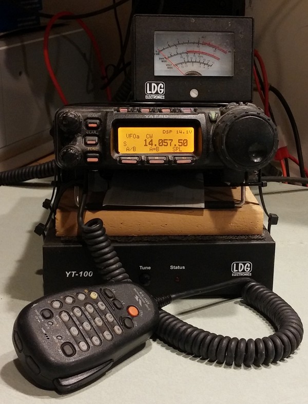
A few years ago, I had an opportunity to pick up a used Yaesu FT-857D from a local Ham that was downsizing.
The FT-857D is an "All Band, All Mode" compact Transceiver. The radio provides 100 Watts of SSB/CW/FM output on 160M thru 6M, 50 Watts output on 2M, and 20 Watts output on 70 CM.
The only thing I have added to the set is the LDG YT-100 automatic Antenna Tuner. This radio is currently the ONLY radio I have that gives all mode operation on VHF and UHF Bands.
The FT-857D is a permanent installation in the shack and is often used as a dedicated monitor for 6M activity.
Following my experience working with Elecraft when building the KX1, I was very impressed with the customer support and quality of their products.
When Elecraft announced the KX3, I was immediately interested and just knew that I would someday have to have one.
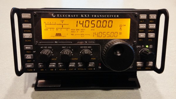
I obtained this Elecraft KX3 Transceiver in September of 2012. The KX3 is a QRP (low power) radio intended for portable operating.
The radio is very impressive and has the best receiver of all my current radios. The KX3 provides 10 Watts of SSB/CW/DATA/AM/FM modes on 160M thru 6M,
and has an internal antenna tunner and battery charger.
In April 2013, I upgraded from the IC-756ProIII to this Icom IC-7600. The IC-7600 has several
improvements over the IC-756ProIII and I still have the 756ProIII as a backup HF rig and I also often
use it for Field Day operations.
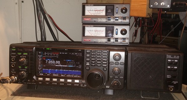
Like the IC-756ProIII, and many other radios, the IC-7600 has two antenna connections. Each antenna
connector is connected directly through a Diamond Model SX-200 Power/SWR meter. On the right is the
Icom SP-23 External Speaker.
A close look at the IC-7600 Spectrum scope shows the waterfall option that was implemented with firmware release v2.0 in 2015.
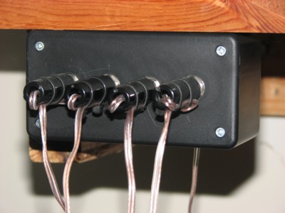
As mentioned many other places on this website, I am an avid CW (Morse Code) operator.
A part of the fun of using Morse Code is using different keys. I often change keys from
one QSO (conversation) to another and might even change keys in the middle of the same
QSO. It is often convenient to be able to rapidly switch from a straight key to a
semi-automatic bug, for example.
The Icom IC-756PROIII radio provides two connectors for Morse Code keys. The front
panel key jack can be used for a straight key or a set of paddles for use with the internal
keyer. There is also a rear panel jack for use of a straight key. This home-made junction
box allows me to plug four keys simultaneously into a single jack on the radio.
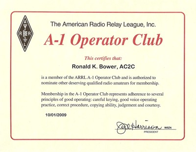
In October, 2009, I was very pleasantly surprised to receive notification that I
had become a member of the ARRL's A-1 Operator Club. Membership in this club is
attained by being nominated and seconded by two current members of the club.
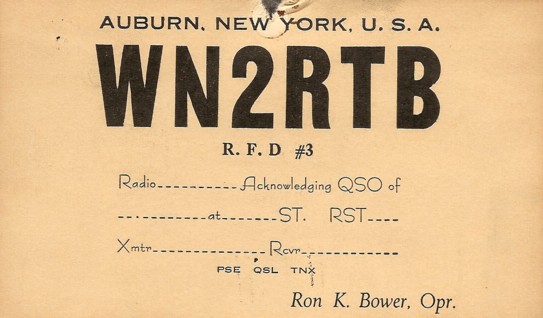
This was my QSL Card in my Novice class days.
I lived in such a small community that I once received a QSL card addressed to "Ron, Auburn, NY".
The cards were designed by me and printed by a local printer. I really could've used an Elmer - Note a few unique things:
- I did not specify a mode -- CW was all that I could do.
- I forgot to have a space for the frequency -- it was the Novice band.
- I didn't know about Greenwich Time. I used either EST or EDT.
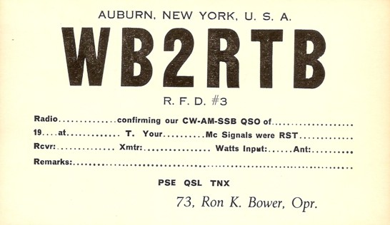
This was my QSL Card in my early General class days. Note that the only modes I used were CW, AM, and SSB.
Actually, I never had a radio with SSB capability until 1973 in Hawaii - It may have been more wishful thinking than anything else.
This was in a time before Hertz had been defined as a unit of cycles per second. Frequencies were stated in MegaCycles or Mc.
By this time in my Ham career, I had realized that I could use GMT.
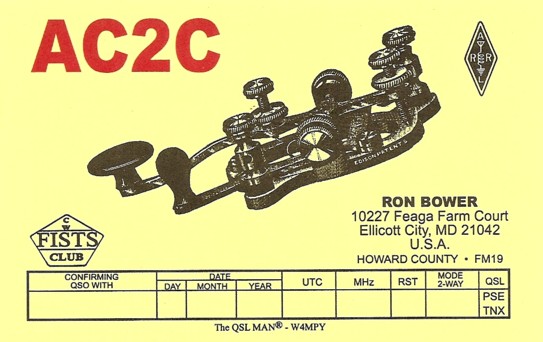
This was my first QSL card after returning to Ham Radio activities in 2006.
It was a very nice card, done by W4MPY. I went through my first 250 of them fairly quickly.
At the time I ordered these cards, I was still working to rebuild my CW skills and
speed after 25 years of inactivity. I was already a member of FISTS and wanted a card
that portrayed my interest in Morse Code.
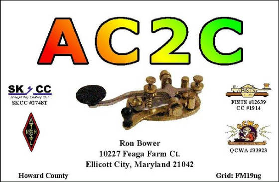
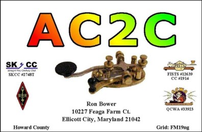
This is my current QSL card.
In this card, I also wanted to convey my interest in Morse Code and also list my association with SKCC and FISTS.
This card was printed by CheapQSLs. They worked closely with me to get the right layout and color scheme.
|
